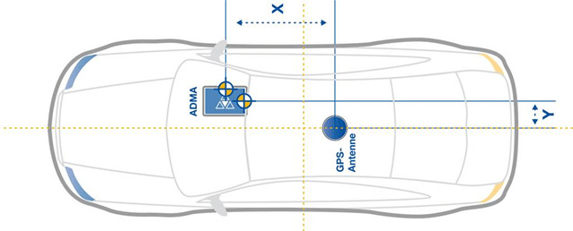
The ADMA, the GNSS antenna and external speed sensor can’t be mounted at the very same spot. The devices are placed at different positions in or outside the vehicle.
Usually:
• GNSS antenna is mounted on the roof
• ADMA close to the center console or in the boot
• External velocity sensor on the side, front or rear of the vehicle.
The distance between the individual components is termed “lever arm”.
As a consequence, the position measured by the GNSS antenna does not correspond to the virtual measuring point (reference point: Point Of Interest). An uncompensated lever arm also causes roll, pitch and course changes which need to be registered as errors in the form of position discrepancies. With data output V3.x it is possible to define up to eight POI’s.
Furthermore, the speed measured at the installation position of the external velocity sensor is not equal to the speed at the virtual measuring point. While the vehicle is travelling through a corner or in a circle, the speed measured by a sensor which is mounted on the vehicle’s outer side is higher than the speed measured in the middle of the vehicle or inside the vehicle.
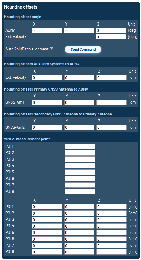
Installation positions are compensated by specifying the position vectors ADMA relative to GNSS antenna and ADMA relative to external speed sensor. With these lever arms the GNSS sensor data and the sensor data of the external speed sensor are factored into the calculation of the position such ensuring the correct transformation of ADMA related data to the POI. The position vectors are entered and edited in the ADMA Webinterface Offsets dialog. For determination of the installation position a folding rule or reference tape is completely adequate.

Single antenna mounting offsets
The position vector for the GNSS antenna consists of all three components (X, Y, Z) and refers to the ADMA.


Virtual measuring point (POI – point of interest)
If the ADMA is not mounted directly at the required measuring location, then a lever arm exists between the virtual measurement point (Point Of Interest / POI) and Measuring Reference Point of the ADMA (MRP). This lever arm can be compensated by entering the offsets to the virtual measurement point.
• X (positive in travel direction)
• Y (positive leftward with respect to direction of travel)
• Z (positive upward)
With the current data format version up to eight POIs can be defined in parallel.
Note: This compensation is only valid, assuming that the car turns around a virtually fixed axis and the movement of this axis in the horizontal plane is insignificant relative to the vehicle. However, this compensation is incorrect, if the axis doesn’t fulfil the above mentioned condition. For example, this could happen in driving situations like spinning or drifting i.e. the axis moves obviously.


