ADMA misalignment
As described earlier, an exact alignment of the measurement axes with the vehicle’s axes is rarely achieved. However, it is possible to compensate such alignment errors mathematically.
Compensation values can be entered in the Offsets dialog in the ADMA Webinterface (menu 6️⃣ PARAMETERS).
Sequence of ADMA misalignment angle compensation
The sequence of misalignment angle compensation is mathematically defined by the rotary matrices which are applied (X, Y, Z = Roll, Pitch, Yaw).
With the setup routine given by the ADMA Webinterface (menu 6️⃣ PARAMETERS) the first two axes can be compensated. Once executed, only the misalignment in Yaw (Z) remains, which can be entered using the configuration menu of the ADMA Webinterface.
To avoid errors in compensating, all three misalignments saved in the ADMA configuration are set to zero prior to execution of the setup routine, compensating Roll and Pitch misalignment. This approach will assure that the setup routine will be executed upon the body fixed (non-compensated) coordinate system of the ADMA. Finally, the compensation of the yaw misalignment has to be entered.
After successful compensation of the misalignment angles all axes are mathematically rotated correctly, thus the measurement data will correspond to a horizontal and in driving direction mounted ADMA. Further transformations (e.g. lever arms), which follow the misalignment compensation in code, are not affected.
Horizontal compensation of an ADMA misalignment
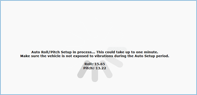
Bring the vehicle into the desired reference orientation and start the setup routine for the roll and pitch angle at the Webinterface menu 6️⃣ PARAMETERS. The setup routine „Auto Roll / Pitch Alignment“ will give you an estimate of the two angles within one minute and saves those in the ADMA internal setup configuration after finishing the routine.
Note: Make sure the vehicle is not exposed to vibrations during the Auto Setup period.

While the routine is running, the estimated offset angles are displayed. However, the data can also be read from the ADMA after the set-up measurement.
Note: If the ADMA is operated only with an external velocity signal, then the position calculation is made via dead reckoning methods. The dead reckoning calculates the position with integrated velocity and the course angle. The height can be calculated accordingly, using the pitch angle instead of the course angle. However, the pitch angle misalignment must be compensated for the height measurement.
Compensation of ADMA’s vertical (Z) axis misalignment
The ADMA’s Z-axis misalignment with respect to its longitudinal axis cannot be ascertained as easily as the horizontal angles. Small misalignments (+/- 5 deg) of the Z-axis are automatically compensated by the Kalman filter.
For larger misalignment errors it is possible to perform a setup test involving longitudinal acceleration produced in stop & go travel. The ADMA’s Z-axis misalignment about its vertical axis causes the levelled acceleration acting along the X-axis to produce a component along the Y-axis as well. This relationship can be used to compute an angle of misalignment based on the measured data. Similar to the horizontal angles, the obtained value is entered in the Z field of the section labelled Mounting offset angles. If not executed carefully, this method may produce errors.
Compensation of the vertical-axis misalignment by an 2-axis speed sensor
If a 2-axis speed sensor – for instance, one made by Corrsys – is employed, its mounting can be rotated. The corresponding misalignment can only be determined during a straight-ahead run. Similar to the misalignment in the case of the ADMA, a misalignment causes the vehicle’s X-axis speed to produce a component along the sensor’s Y-axis. This data can be used to calculate the angle of misalignment. The obtained value is entered in the field Z Ext. velocityin the section labelled Mounting offset angles.


