


Inertial Reference System ADMA-G for vehicle dynamics testing
The Automotive Dynamic Motion Analyzer (ADMA) is more than just an inertial reference system and has been specially developed for vehicle dynamics measurements in the automotive sector. Equipped with DGNSS (Differential Global Navigation Satellite System) and fiber optic gyroscopes, this highly accurate inertial reference system defines new standards for vehicle dynamics applications in the automotive sector. Our inertial reference track system ADMA allows for constant measurement of acceleration, speed and position of moving vehicles in all three dimensional axes. Pitch, roll and course angles can be continuously and precisely measured with ADMA as well as course and side-slip angles as well as angular rates.
This makes the GeneSys’ ADMA inertial measurement unit (IMU) the best choice among inertial reference systems where challenging measurements with maximum accuracies are required.
Technical data of ADMA-G-PRO+, ADMA-G-ECO+, and ADMA-G-ECO can be found in the tables below or in the datasheet.
Our systems are not subject to US export restrictions and can be used worldwide without the need for approval.
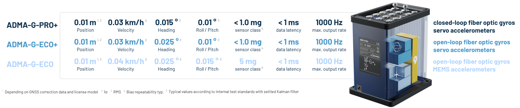
GeneSys’ Inertial Reference Systems at a glance
Applications with Inertial Reference System ADMA
The strap-down technology ensures that the inertial reference system ADMA is stable and resistant to unwanted vibration during use. This means the ADMA is very well suited for evaluation of Vehicle Dynamics and Driver Assistance Systems. The ADMA system is successfully used for Motorsports, Driver-less Systems, and Construction Machines. It is proven itself in the areas of Route, Track Wear, and Railway measurements.
ADMA Features
-
Measurement of vehicle motion in three axes, even during GNSS signal loss
-
Dynamic attitude and heading angle determination
-
Precise acceleration, speed, and position data due to extended Kalman filter
-
Precise position data with integrated WAAS/EGNOS-DGNSS receiver (<1m)
-
High precision position data (1 cm) with internal RTK DGNSS receiver and GNSS Base Station
-
Robust inertial sensors and strap-down technology without moving parts
Highlights Inertial Reference Systems ADMA-G
-
Data output rate up to 1000 Hz
-
Data output via 5 CAN bus interfaces and Ethernet
-
Configuration via Ethernet
-
Forwarding of GNSS correction data and relative data calculation (e.g. distance) via WiFi in real-time for multi-vehicle operation
-
GNSS synchronized DAQ synchronization signal, the high clock frequency
-
Inputs for the recording of analog signals
-
The output of GNSS raw data via Ethernet interface
-
Indoor GNSS interface
-
Dual GNSS antenna option
-
Multi GNSS capable (GPS, GLONASS, GALILEO, BEIDOU)
-
Data latency < 1 ms
-
Compatible with all common steering and driving robots
Inertial Reference Systems for any requirements
The models of the inertial reference system ADMA-G differ in the performance of the applied inertial sensors. Higher precision sensors are less sensitive to GNSS interferences or outages. All models are available with variable GNSS accuracy, ranging from simple L1 receivers with meter accuracy to L1/L2 RTK receivers with centimeter accuracy. Our gyro systems do not require an export license (ITAR FREE).


ADMA-options – extending capabilities
ADMA 3.5’s new generation IMUs cater to evolving customer needs with enhanced usability and productivity. Activate add-on functions seamlessly with a license key, ensuring hardware remains unaltered for utmost flexibility.
Overview ADMA-Options and Add-Ons
-
Add-On DELTA: Relative data calculation via WiFi in real-time for multi-vehicle operation
-
Add-On BRAKING: Real-time calculation of brake performance data according to international regulations
-
Add-On LATDEV: Real-time calculation of the lateral deviation
-
Add-On FILTER: Add-On for online signal filtering
-
Option DGNSS correction data: Correction data via Ethernet
-
Option GNSS-Raw Data: Output of GPS raw data via Ethernet interface
-
Option Dual-Ant: Two GNSS antennas option
-
Option 1kHz: Data output rate of 500 Hz and 1 kHz via CAN or Ethernet interface
-
Option Multi-CAN: Data output via several CAN channels simultaneously
Accessories
Our ADMA accessories ensure fast, precise and reliable work.
Technical data of ADMA-G Inertial Reference System
ADMA-G-PRO+
| COMPLETE SYSTEM | |
| GNSS constellations | GPS L1, L2 GLONASS L1, L2 BeiDou*1 B1, B2 Galileo*1 E1, E5 |
| Dual antenna | Optional |
| Position accuracy (1σ)*2 | 0.01 / 0.20 / 0.60 / 1.20 / 1.50 m |
| Angle Measurement range roll / pitch / yaw | 60 ° / 60 ° / ± 180 ° |
| Angle Measurement accuracy roll & pitch (1 σ) / yaw (1 σ) / sideslip (RMS) | 0.01 / 0.015 / 0.05 ° |
| Angle resolution | 0.005 ° |
| Velocity accuracy (RMS)*3 | 0.03 km/h |
| Position error after 10 / 30 / 60 sec GNSS outage (RMS)*3 | 0.1 / 0.6 / 2.0 m |
| Velocity error after 10 / 30 / 60 sec GNSS outage (RMS)*3 | 0.01 / 0.03 / 0.06 m/sec |
| Roll / Pitch angle error after 10 / 30 / 60 sec GNSS outage (RMS)*3 | < 0.01 / 0.01 / 0.01 ° |
| Heading angle error after 10 / 30 / 60 sec GNSS outage (RMS)*3 | < 0.01 / 0.01 / 0.01 ° |
| Braking distance accuracy without RTK (RMS)*3 | 0.05 m |
| Data output rate | 50 / 100 / 200 / 250 / 500 Hz / (1000 Hz)*1 |
| Calculation latency | 1 msec |
| – | |
| SENSORS – GYROS | |
| Sensor Technology | 3 closed-loop fiber optic gyros |
| Measurement range | ± 327 °/s |
| Data output resolution | 0.0001 °/s |
| Bias repeatability typ. (1 σ) | 6 °/h (0.0017 °/s), optional 1 °/h (0.00028 °/s) |
| In-run-bias typically | 0.1 °/h |
| Noise (random walk) typ. | 0.047 °/√h |
| Scale factor | 0.05 % |
| Sensor bandwidth | 3200 Hz |
| – | |
| SENSORS – ACCELEROMETERS | |
| Sensor Technology | 3 servo accelerometers |
| Measurement range | ± 5 g / (± 10 g)*1 |
| Data output resolution | 0.0001 g |
| Bias repeatability typ. | < 1.0 mg |
| In-run-bias typ. (1 σ) | 10 µg |
| Noise (random walk) typ. | < 50 µg /√Hz |
| Scale factor (1 σ) | 0.015% |
| Sensor bandwidth | 1500 Hz |
| – | |
| INTERFACES | |
| Ethernet | 2x 1 GBit Data input/output, configuration and firmware update, driving robot data output, optional for relative data calculation and DGNSS routing. 1x 100 MBit GNSS Receiver; GNSS firmware update |
| CAN | 1x CAN, 5x CAN*1, 2b, 1 Mbit Data output, input*1 |
| Serial | 1x RS232 GNSS Receiver; DGNSS correction data input 1x RS232 GNSS Receiver; GPGGA Log output, IPS (Indoor Positioning System) |
| Digital/Analog Input | 4x Digital / Analog (16 bit) e.g. Frequency, Brake trigger, … 1x Digital / Analog (16 bit) external velocity X |
| Digital Output | 4x Digital TTL e.g. PPS, Frequency, PPD Pulse per distance, … |
| Connector type | Lemo |
| GNSS | 2x TNC GNSS Antenna connectors |
| – | |
| HARDWARE/MISCELLANEOUS | |
| Ordering Variants | – |
| Internal Memory | up to 64 GB |
| Power supply | 9 to 32 VDC typ. 30 W |
| Dimensions (W x L x H) | 110 x 170 x 197 mm |
| Weight | 3.6 kg |
| Operating temperature | -20 to +60 °C |
| Protection class *4 | IP 65 |
*2 Depending on GNSS conditions, correction data and license model
*3 Typical values according to internal test standards with settled Kalman filter.
*4 The housing is protected against dust and water jets in accordance with IP65. Please note that not all plug connections and
cables are fully sealed in accordance with the IP standard. The cable is therefore not intended for use in permanently wet or damp
environments.
ADMA-G-ECO+
| COMPLETE SYSTEM | |
| GNSS constellations | GPS L1, L2 GLONASS L1, L2 BeiDou*1 B1, B2 Galileo*1 E1, E5 |
| Dual antenna | Optional |
| Position accuracy (1σ)*2 | 0.01 / 0.20 / 0.60 / 1.20 / 1.50 m |
| Angle Measurement range roll / pitch / yaw | 60 ° / 60 ° / ± 180 ° |
| Angle Measurement accuracy roll & pitch (1 σ) / yaw (1 σ) / sideslip (RMS) | 0.01 / 0.025 / 0.1 ° |
| Angle resolution | 0.005 ° |
| Velocity accuracy (RMS)*3 | 0.03 km/h |
| Position error after 10 / 30 / 60 sec GNSS outage (RMS)*3 | 0.2 / 1.0 / 5.0 m |
| Velocity error after 10 / 30 / 60 sec GNSS outage (RMS)*3 | 0.02 / 0.10 / 0.20 m/sec |
| Roll / Pitch angle error after 10 / 30 / 60 sec GNSS outage (RMS)*3 | 0.01 / 0.02 / 0.03 ° |
| Heading angle error after 10 / 30 / 60 sec GNSS outage (RMS)*3 | 0.02 / 0.07 / 0.15 ° |
| Braking distance accuracy without RTK2 (RMS)*3 | 0.05 m |
| Data output rate | 50 / 100 / 200 / 250 / 500 Hz / (1000 Hz)*1 |
| Calculation latency | 1 msec |
| – | |
| SENSORS – GYROS | |
| Sensor Technology | 3 open-loop fiber optic gyros |
| Measurement range | ± 200 °/s |
| Data output resolution | 0.0001 °/s |
| Bias repeatability typ. (1 σ) | 24 °/h (0.0066 °/s) |
| In-run-bias typ. | 1 °/h |
| Noise (random walk) typ. | 0.02 °/√h |
| Scale factor | 0.1 % |
| Sensor bandwidth | 1000 Hz |
| – | |
| SENSORS – ACCELEROMETERS | |
| Sensor Technology | 3 servo accelerometers |
| Measurement range | ± 5 g / (± 10 g)*1 |
| Data output resolution | 0.0001 g |
| Bias repeatability typ. | < 1.0 mg |
| In-run-bias typ. (1 σ) | 10 µg |
| Noise (random walk) typ. | < 50 µg /√Hz |
| Scale factor (1 σ) | 0.015% |
| Sensor bandwidth | 1500 Hz |
| – | |
| INTERFACES | |
| Ethernet | 2x 1 GBit Data input/output, configuration and firmware update, driving robot data output, optional for relative data calculation and DGNSS routing. 1x 100 MBit GNSS Receiver; GNSS firmware update |
| CAN | 1x CAN, 5x CAN*1, 2b, 1 Mbit Data output, input*1 |
| Serial | 1x RS232 GNSS Receiver; DGNSS correction data input 1x RS232 GNSS Receiver; GPGGA Log output, IPS (Indoor Positioning System) |
| Digital/Analog Input | 4x Digital / Analog (16 bit) e.g. Frequency, Brake trigger, … 1x Digital / Analog (16 bit) external velocity X |
| Digital Output | 4x Digital TTL (e.g. PPS, Frequency, PPD Pulse per distance, …) |
| Connector type | Lemo |
| GNSS | 2x TNC GNSS Antenna connectors |
| – | |
| HARDWARE/MISCELLANEOUS | |
| Ordering Variants | – |
| Internal Memory | up to 64 GB |
| Power supply | 9 to 32 VDC typ. 30 W |
| Dimensions (W x L x H) | 110 x 170 x 197 mm |
| Weight | 3.6 kg |
| Operating temperature | -20 to +55 °C |
| Protection class *⁴ | IP 65 |
*2 Depending on GNSS conditions, correction data and license model
*3 Typical values according to internal test standards with settled Kalman filter.
*4 The housing is protected against dust and water jets in accordance with IP65. Please note that not all plug connections and
cables are fully sealed in accordance with the IP standard. The cable is therefore not intended for use in permanently wet or damp
environments.
ADMA-G-ECO
| COMPLETE SYSTEM | |
| GNSS constellations | GPS L1, L2 GLONASS L1, L2 BeiDou*1 B1, B2 Galileo*1 E1, E5 |
| Dual antenna | Optional |
| Position accuracy (1σ)*2 | 0.01 / 0.20 / 0.60 / 1.20 / 1.50 m |
| Angle Measurement range roll / pitch / yaw | 60 ° / 60 ° / ± 180 ° |
| Angle Measurement accuracy roll & pitch (1 σ) / yaw (1 σ) / sideslip (RMS) | 0.015 / 0.025 / 0.1 ° |
| Angle resolution | 0.005 ° |
| Velocity accuracy (RMS)*3 | 0.04 km/h |
| Position error after 10 / 30 / 60 sec GNSS outage (RMS)*3 | 0.3 / 2.0 / 10.0 m |
| Velocity error after 10 / 30 / 60 sec GNSS outage (RMS)*3 | 0.04 / 0.15 / 0.35 m/sec |
| Roll / Pitch angle error after 10 / 30 / 60 sec GNSS outage (RMS)*3 | 0.02 / 0.03 / 0.05 ° |
| Heading angle error after 10 / 30 / 60 sec GNSS outage (RMS)*3 | 0.03 / 0.10 / 0.20 ° |
| Braking distance accuracy without RTK2 (RMS)*3 | 0.05 m |
| Data output rate | 50 / 100 / 200 / 250 / 500 Hz / (1000 Hz)*1 |
| Calculation latency | 1 msec |
| – | |
| SENSORS – GYROS | |
| Sensor Technology | 3 open-loop fiber optic gyros |
| Measurement range | ± 200 °/s |
| Data output resolution | 0.0001 °/s |
| Bias repeatability typ. (1 σ) | 24 °/h (0.0066 °/s) |
| In-run-bias typ. | 1 °/h |
| Noise (random walk) typ. | 0.02 °/√h |
| Scale factor | 0.1 % |
| Sensor bandwidth | 1000 Hz |
| – | |
| SENSORS – ACCELEROMETERS | |
| Sensor Technology | 3 MEMS accelerometers |
| Measurement range | ± 2 g / (± 5 g)*1 |
| Data output resolution | 0.0001 g |
| Bias repeatability typ. | 5 mg |
| In-run-bias typ. (1 σ) | 10 µg |
| Noise (random walk) typ. | 50 µg /√Hz |
| Scale factor (1 σ) | 0.2% |
| Sensor bandwidth | 100 Hz |
| – | |
| INTERFACES | |
| Ethernet | 2x 1 GBit Data input/output, configuration and firmware update, driving robot data output, optional for relative data calculation and DGNSS routing. 1x 100 MBit GNSS Receiver; GNSS firmware update |
| CAN | 1x CAN, 5x CAN*1, 2b, 1 Mbit Data output, input*1 |
| Serial | 1x RS232 GNSS Receiver; DGNSS correction data input 1x RS232 GNSS Receiver; GPGGA Log output, IPS (Indoor Positioning System) |
| Digital/Analog Input | 4x Digital / Analog (16 bit) e.g. Frequency, Brake trigger, … 1x Digital / Analog (16 bit) external velocity X |
| Digital Output | 4x Digital TTL (e.g. PPS, Frequency, PPD Pulse per distance, …) |
| Connector type | Lemo |
| GNSS | 2x TNC GNSS Antenna connectors |
| – | |
| HARDWARE/MISCELLANEOUS | |
| Ordering Variants | – |
| Internal Memory | up to 64 GB |
| Power supply | 9 to 32 VDC typ. 30 W |
| Dimensions (W x L x H) | 110 x 170 x 197 mm |
| Weight | 3.6 kg |
| Operating temperature | -20 to +55 °C |
| Protection class*4 | IP 65 |
*2 Depending on GNSS conditions, correction data and license model
*3 Typical values according to internal test standards with settled Kalman filter.
*4 The housing is protected against dust and water jets in accordance with IP65. Please note that not all plug connections and
cables are fully sealed in accordance with the IP standard. The cable is therefore not intended for use in permanently wet or damp
environments.