Once the IPS is installed, the measurement setup has to be made for getting the first measurement data.
Hardware Setup
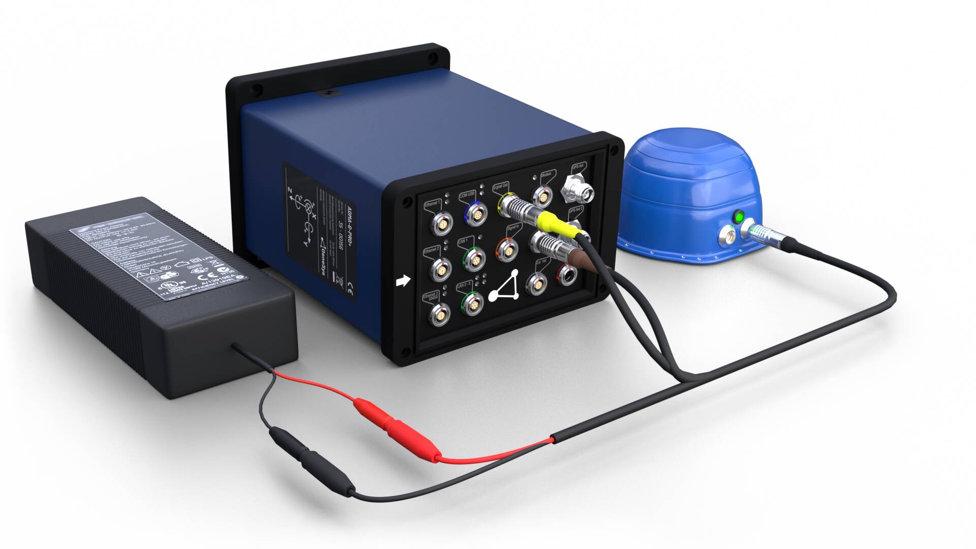
For the Hardware setup please stick to the graphic below.

Software Setup
For using the ADMA in combination with the IPS for indoor purposes, the following settings have to be made in the ADMA Webinterface and in the VIPS Site Configuration.
ADMA Webinterface
In this section only the IPS depended settings are shown. For the basic setup of the ADMA system, please refer to the ADMA Manual. The change of the receiver hardware requires a power reset!
In the first step, Used receiver type has to be configured to IPS at 5️⃣ AUX SYSTEMS.

At 6️⃣ PARAMETERS, the mounting offsets from the rover unit to the ADMA measurement center have to be defined. We recommend to measure the offsets with an accuracy of 2 cm. For configuring the correct sign please refer to the images given in the ADMA Webinterface information side bar for each axis.

The measurement center of the ADMA is shown with markers on the HW surface.

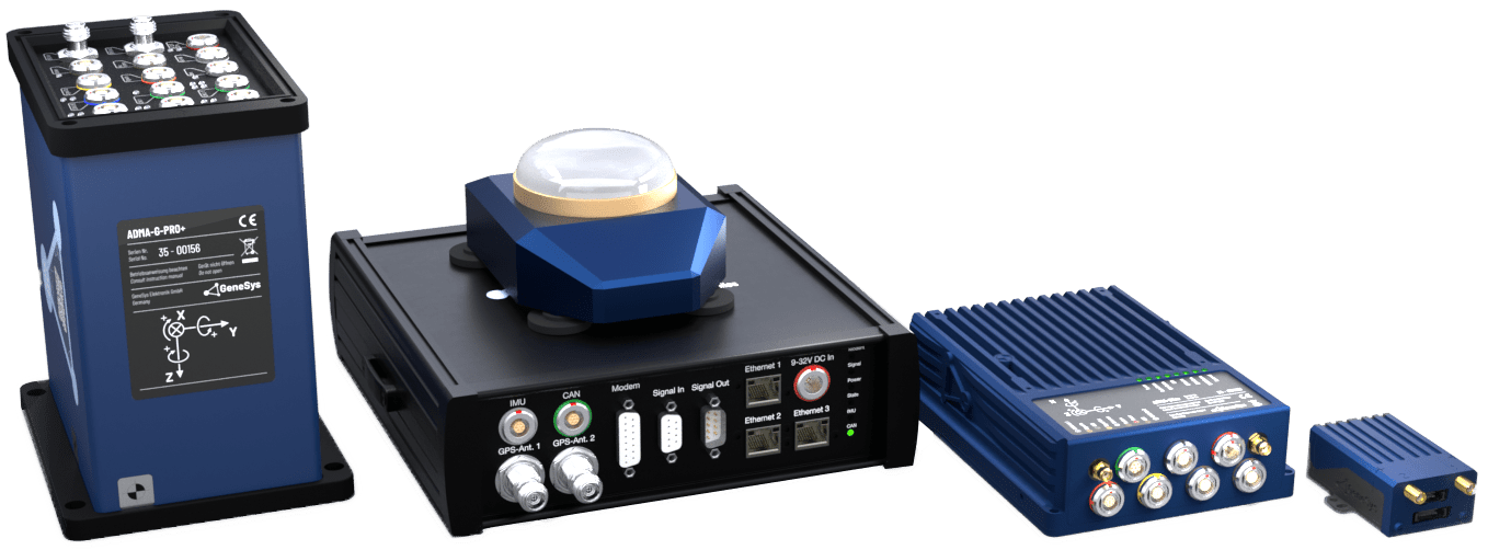
For measuring the offset of the rover measurement center to the ADMA refer to the point shown in the graphic below.

VIPS Site Configuration
System Settings
Please open the VIPS Site Configuration Software and configure the values as followed:
| Mode: | External sync |
| Origin: | Desired origin |
| Elevation correction: | |
| Kalman filter: | Disabled |
| Block beacon detection: | Disabled |
| Output: | Racelogic Binary |
| Output rate: | 20 Hz |

Beacon positions
In the next step, the positions of each beacon has to be determined via survey. Please place the vehicle with the installed rover at a central position and measure the positions of all beacons with a handheld laser or a Total Station within a accuracy of 1cm. The single positions of the beacons have to be input into the table below.

At the MAP menu, the offsets can be checked for plausibility.

Upload Configuration
Now the settings should be uploaded to the rover with the IPS Rover serial config cable (RLCAB151).
IPS Delay Calibration
The Calibration of the collective antennas will result in improved accuracy. The process needs to be completed in ten steps.
Step 1 For the delay calibration it is important that the rover is in a central position between the beacons. If it didn’t get moved after the survey of the handheld laser or the Total Station, these position data can be used for the calibration. If not, the position of the rover has to be determined accurately.
Step 2 Establish a connection to the rover via serial cable (RLCAB151) and power the rover. Open the ‘VIPS site verification and diagnostics’ software. Change the rover type to beacon by hitting the Rover To Beacon button. The LED of the Rover will temporarily shine white and then starts flashing green.

Step 3 Load the configuration file of the current beacon setup with the measured positions by drag and drop.

Step 4 Ensure that the area between the beacons is free of obstacles. Connect to any beacon (central beacon prefered) via serial cable (RLCAB151). Take care not to move the beacon.
Step 5 Load the configuration file again by dragging it into the beacon locations box.
Step 6 Double-Click on the last beacon ID in the list and enter the position data of the rover that got measured by the total station eralier on.
Step 7 Click Connect and Measure. When the process is finished click Calculate and Save results JSON.

Step 8 Again, establish a connection to the rover via serial cable (RLCAB151). Open the ‘VIPS site configuration’ software and configure the following values:
| Enable block beacon detection: | Off |
| Enable elevation correction: | Off |
| Rotation angle: | 0° (If the coordinate system of the IPS shall include the rotation to the real north, please determine the angle offset and configure it here. |

Step 9 Check the plausibility of the beacon delay values. The determined values should be within a range of less than 0.10 m.

Step 10 Save the configuration to the Rover. The system is now ready for usage. The IPS needs around 1 minute of initialization before being able to output valid positioning data.


