Inertial Navigation System ADMA-Speed: Precise Speed and Braking Distance Sensor
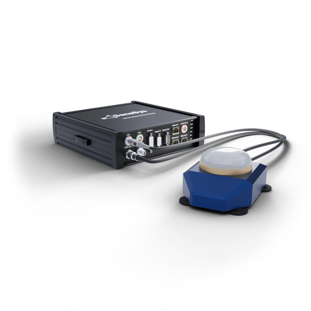
ADMA-Speed is an Inertial Navigation System with integrated inertial sensors. It is optimized for brake tests. For easy installation, the inertial sensors are integrated in the GNSS antenna.
All motion data of the vehicle is calculated by means of the tried and tested ADMA technology. In the basic version of the Inertial Navigation System ADMA-Speed, acceleration, speed and braking distance is transmitted via the CAN and Ethernet interface. ADMA-Speed eliminates the known disadvantages of GNSS speed sensors.
Technical data for Inertial Navigation System ADMA-Speed can be found in the table below or in the data sheet.

Our systems are not subject to US export restrictions and can be used worldwide without the need for approval.
ADMA-Speed: Our Inertial Navigation System at a glance

Meets requirements of international test standards EURO NCAP and NHTSA
-
GNSS speed sensor optimized for brake tests
-
ADMA-Speed eliminates the known disadvantages of GNSS speed sensors
-
Validation of driver assistance systems e.g. ACC, FCW, AEB (VRU, Car2Car), LSS (LDW, LKA)
-
Chassis adjustment
Highlights of our Inertial Navigation System
-
User-friendly handling thanks to the combination of GNSS antenna and inertial sensors in one housing
-
Mounting by means of powerful magnets on the vehicle roof
-
Pitch compensation during braking
-
Considerably smoother speed signal in comparison to GNSS
-
Compensation of GNSS data latency
-
Correction of acceleration-dependent GNSS signal distortion
-
Speed calculation at the vehicle center of gravity
-
Data processing unit with tried and tested Kalman filter technology
-
Output of acceleration, speed and braking distance via CAN interface in real-time (up to 1 kHz)
-
Signal inputs for braking trigger or light barrier
-
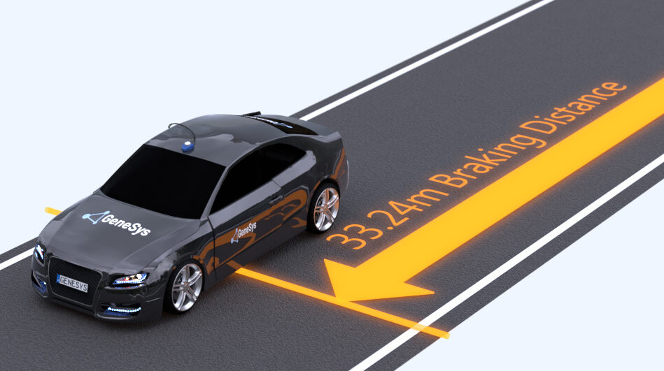
Speed and signal-triggered braking distance

Options and accessories for the Inertial Navigation System ADMA-Speed
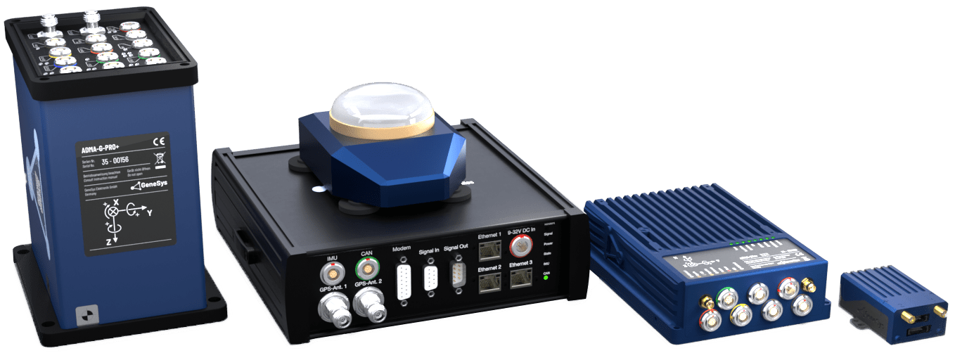
Optionally, ADMA-Speed can be expanded to a full-fledged Inertial Navigation System, e.g. for vehicle dynamics testing or verification of ADAS systems (Advanced driver assistance systems).
-
Output of lateral deviation
-
Output of all motion states (acceleration, velocity, position, angular rate, angle)
-
2 antenna version for course angle without initialization
-
2 cm position accuracy
-
Data output rate 1 kHz
-
Relative data calculation (e.g. range) via WiFi in real-time for multi-vehicle operation

Technical data of the Inertial Navigation System ADMA-Speed
ADMA-Speed
| COMPLETE SYSTEM | |
| GNSS constellations | GPS L1, L2 GLONASS L1, L2 BeiDou*1 B1, B2 Galileo*1 E1, E5 |
| Dual antenna | Optional |
| Position accuracy (1σ)*2 | 0.01 / 0.20 / 0.60 / 1.20 / 1.50 m |
| Angle Measurement range roll / pitch / yaw | 60 ° / 60 ° / ± 180 ° |
| Angle Measurement accuracy roll & pitch (1 σ) / yaw (1 σ) / sideslip (RMS) | 0.02 / 0.05 / 0.15 ° |
| Angle resolution | 0.005 ° |
| Velocity accuracy (RMS)*3 | 0.04 km/h |
| Position error after 10 / 30 / 60 sec GNSS outage (RMS)*3 | 0.4 / 5.0 / 40.0 m |
| Velocity error after 10 / 30 / 60 sec GNSS outage (RMS)*3 | 0.06 / 0.5 / 1.5 m/sec |
| Roll / Pitch angle error after 10 / 30 / 60 sec GNSS outage (RMS)*3 | 0.05 / 0.15 / 0.30 ° |
| Heading angle error after 10 / 30 / 60 sec GNSS outage (RMS)*3 | 0.05 / 0.15 / 0.30 ° |
| Braking distance accuracy without RTK2 (RMS)*3 | 0.05 m |
| Data output rate | 50 / 100 / 200 / 250 / 500 Hz / (1000 Hz)*1 |
| Calculation latency | 1 msec |
| – | |
| SENSORS – GYROS | |
| Sensor Technology | 3 MEMS gyros |
| Measurement range | ± 450 °/s |
| Data output resolution | 0.0001 °/s |
| Bias repeatability typ. (1 σ) | 0.2 °/s |
| In-run-bias typ. | 6 °/h |
| Noise (random walk) typ. | 0.3 °/√h |
| Scale factor | 0.2 % |
| Sensor bandwidth | 330 Hz |
| – | |
| SENSORS – ACCELEROMETERS | |
| Sensor Technology | 3 MEMS accelerometers |
| Measurement range | ± 5 g / ± 15 g*1 |
| Data output Resolution | 0.0001 g / 0.0001 g |
| Bias repeatability typ. | 4 mg / 16 mg |
| In-run-bias typ. (1 σ) | 32 µg / 70 µg |
| Noise (random walk) typ. | 50 µg /√Hz / 63 µg /√Hz |
| Scale factor (1 σ) | 0.2% / 0.2 % |
| Sensor bandwidth | 330 Hz / 330 Hz |
| – | |
| INTERFACES | |
| Ethernet | 2x 1 GBit Data input/output, configuration and firmware update, driving robot data output, optional for relative data calculation and DGNSS routing. 1x 100 MBit GNSS Receiver; GNSS firmware update |
| CAN | 1x CAN 2b, 1 Mbit Data output, input*1 |
| Serial | 1x RS232 GNSS Receiver; DGNSS correction data input 1x RS232 GNSS Receiver; GPGGA Log output, IPS (Indoor Positioning System) |
| Digital/Analog Input | 3x Digital / Analog (16 bit) e.g. Frequency, Brake trigger, … |
| Digital Output | 4x Digital TTL e.g. PPS, Frequency, PPD Pulse per distance, … |
| Connector type | Lemo & Sub-D |
| GNSS | 2x TNC GNSS Antenna connectors |
| – | |
| HARDWARE/MISCELLANEOUS | |
| Ordering Variants | – |
| Internal Memory | up to 64 GB |
| Power supply | 9 to 32 VDC typ. 20 W |
| Dimensions (W x L x H) | Data processing unit 225 x 235 x 75 mm Sensor unit 110 x 130 x 70 mm (with magnets) 87 x 130 x 60 mm (without magnets) |
| Weight | Data processing unit 2.3 kg Sensor unit 0.75 kg |
| Operating temperature | Data processing unit -20 to +60 °C Sensor unit -40 to +85 °C |
| Protection class | Data processing unit IP 50 Sensor unit IP 67 |
*2 Depending on GNSS conditions, correction data and license model
*3 Typical values according to internal test standards with settled Kalman filter.


