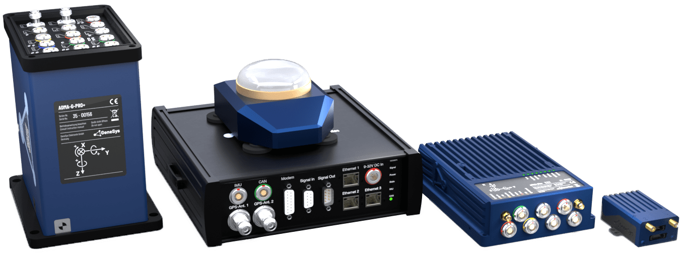
The routine described below is designed to test the functionality of the inertial sensors in the gyro system – specifically the accelerometers and gyroscopes. This function test also serves as a practical introduction to the ADMA system, offering a hands-on opportunity to become familiar with its setup and configuration via the web interface.
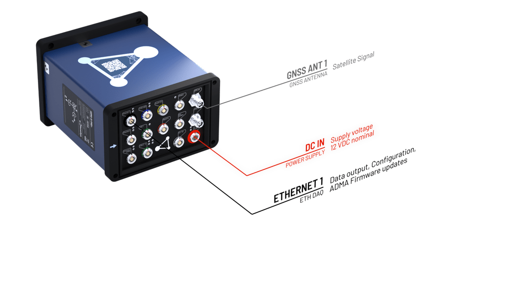
Setup and cabling
The following components should be prepared for the function test:
- ADMA
- ADMA-Power supply cable
- ADMA-Ethernet cable
- Power Supply 9-32V DC
After connecting the ADMA cables to the interfaces, the systems boots up. When both Power LED’s are illuminated, the inertial navigation system is ready for operation.
ADMA configuration for Getting Started
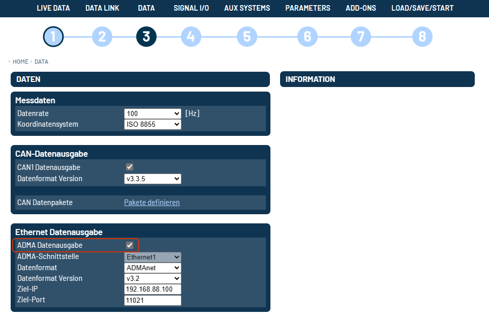
Configuring measurement data transmission via Ethernet interface
Go to menu 3 – Data . Activate ADMAnet data output and configure the Destination IP to the IP address of your PC.
Parameters
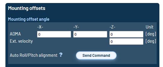
The values of roll and pitch angle misalignment should be determinate via Auto Roll/Pitch alignment at menu 6️⃣ Parameters. After executing this function, the ADMA determines the angle offsets on the table by using the earth gravitation.
Save settings to ADMA
The altered settings must be saved to the inertial navigation system. With Save settings to file, the configuration of the inertial system can be saved for later usage or backup purposes. When hitting start measurement at menu 7️⃣ LOAD/SAVE/START, Save settings will be executed first and then the ADMA starts the measurement mode.
When the ADMA measurement is running, the Measurement active value is 1.
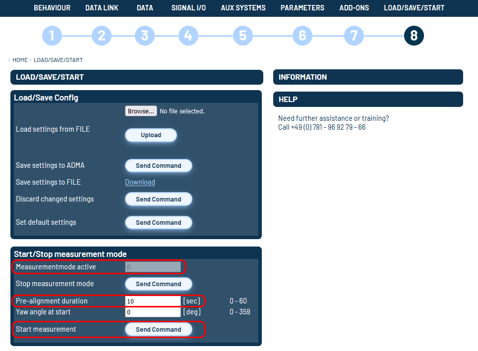
Setup the ADMA Data Logger
Install the ADMA Data Logger with the Single Installer or with the GeneSys Software Suite. Open the Software and load the ADMA settings, if you used the default settings, the ADMA data should be deteceted automatically at startup.
Static test
Checking the system status
Now check the data channels Status_Standstill and Error_Hardware. The value of Status_Standstill should be one. As soon as you move the system by hand or wobble at the table, the Standstill bit should jump to 0.
| Status_Standstill |
|---|
| 1 at standstill |
6.4.3 Checking the accelerations
The inertial navigation system should be positioned on a laboratory bench or similar facility, thus being placed on a close to horizontal surface. In addition, keep a flat support surface ready so that the ADMA remains level even when tilted. Tilt the ADMA in the axes as shown below, the following body-fixed accelerations should then be indicated:
| ADMA ORIENTATION | Acc_Body_X (g) | Acc_Body_Y (g) | Acc_Body_Z (g) |
|---|---|---|---|
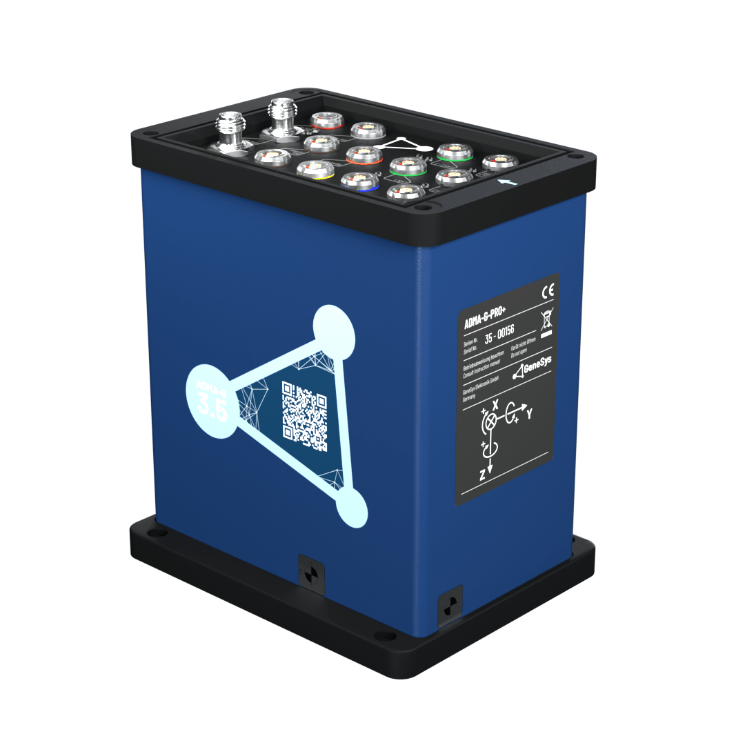 | 0 | 0 | -1 |
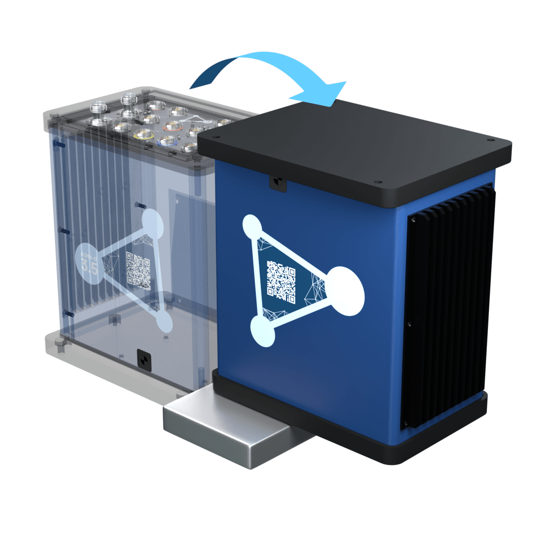 | 0 | 0 | 1 |
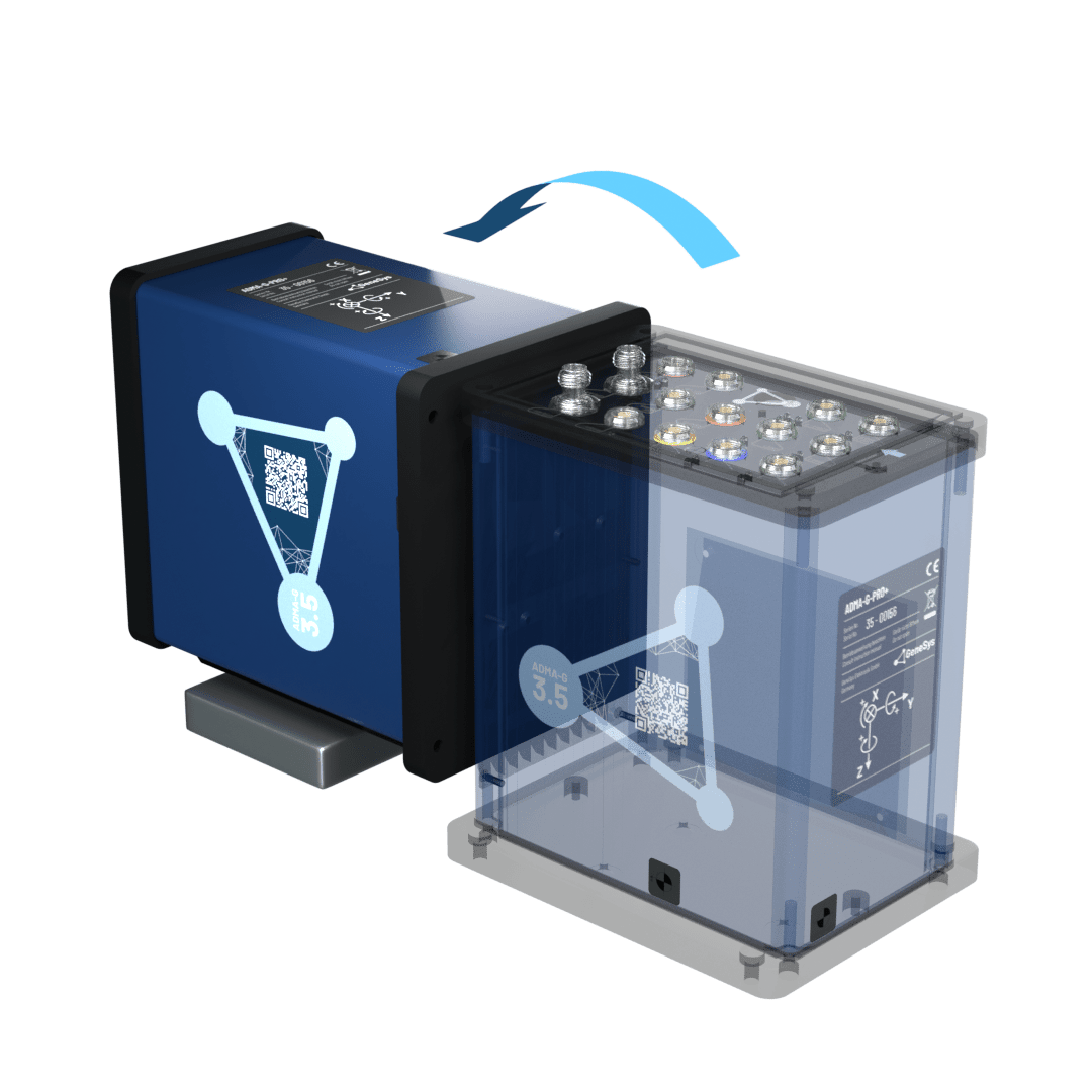 | -1 | 0 | 0 |
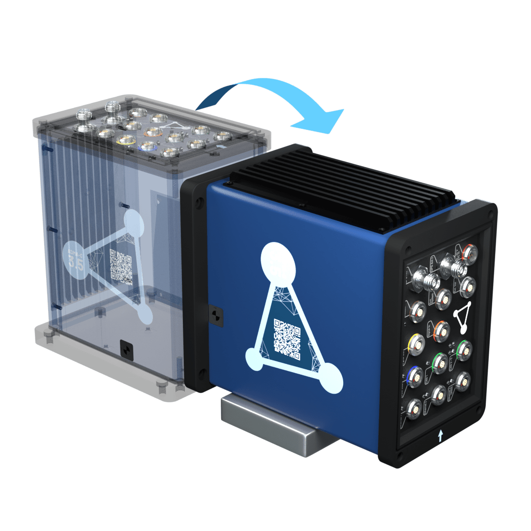 | 1 | 0 | 0 |
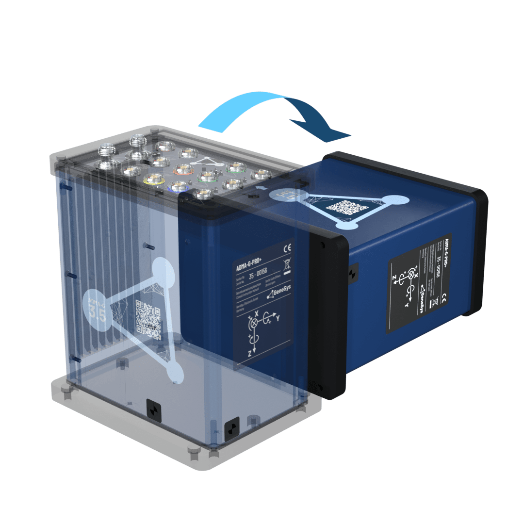 | 0 | -1 | 0 |
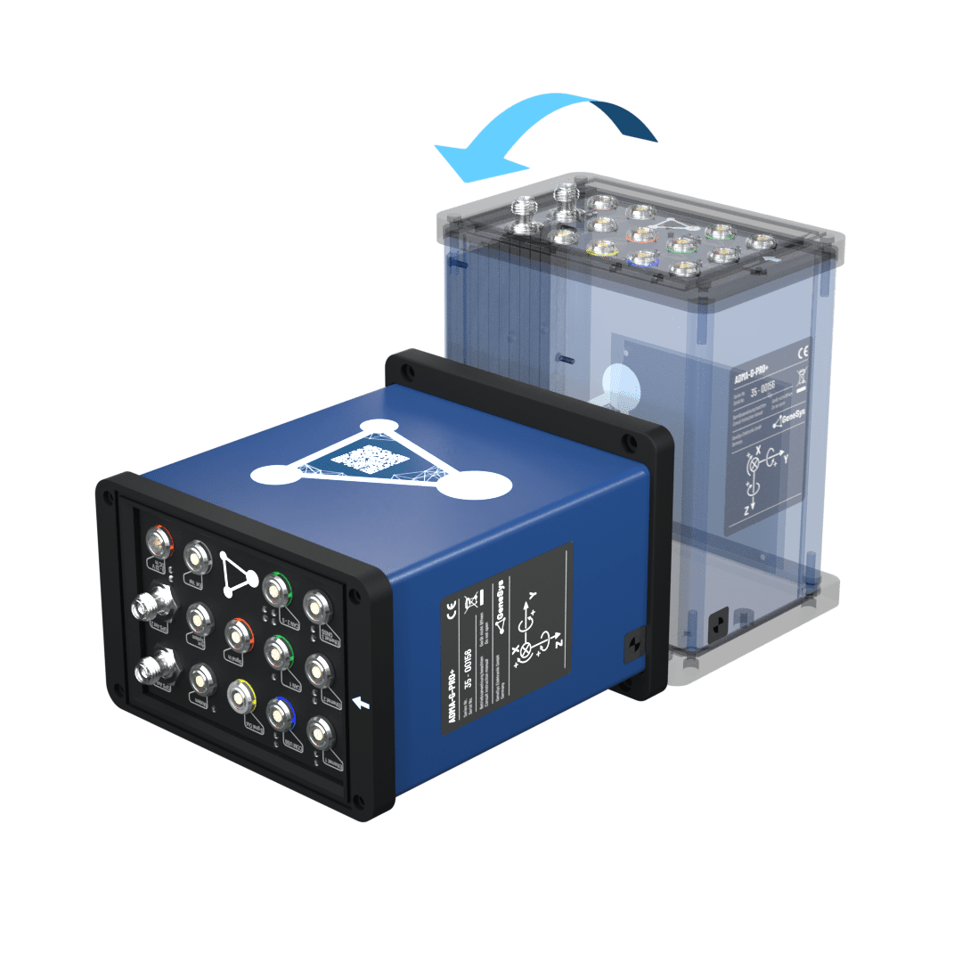 | 0 | 1 | 0 |
The measured acceleration of the observed axis should be between 1.01 g and 0.99 g. This test is helpful to ensure that the accelerometers have not been damaged.
Additionally, you’ll gain insight into how the horizontal and body coordinate systems function. The body coordinate system is fixed to the ADMA hardware, meaning it rotates with the device. In contrast, the horizontal coordinate system remains aligned with the horizon. When the system is tilted, the gravitational force shifts between the axes of the body coordinate system. However, in the horizontal coordinate system, the 1g gravitational force consistently remains aligned with the Z-axis no matter the orientation of the ADMA.
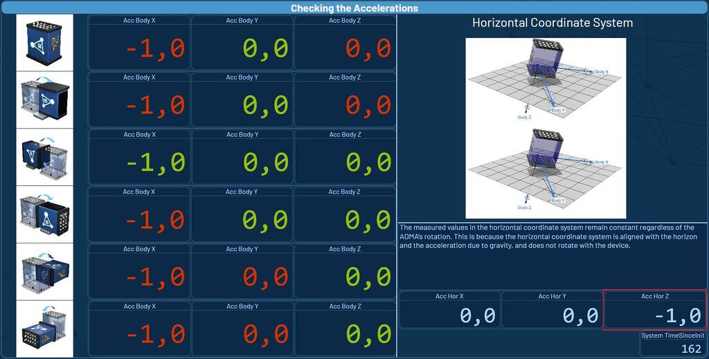
Checking the rotational speed
In a static state, the following rotational speeds should be indicated:
| ADMA ORIENTAION | Rate_Body_X (°/s) | Rate_Body_Y (°/s) | Rate_Body_Z (°) |
|---|---|---|---|
 | 0.024 | 0.026 | 0.038 |
The measured rotational speed of all axis should be between ±0,1°/s.
Without special software and hardware, it is not possible to test gyros accurately, so it is necessary to send the ADMA to GeneSys for calibration on a regular basis. We recommend a calibration interval of 2 years.
Dynamic Test
As part of the dynamic test, the ADMA undergoes defined linear and rotary motion, i.e. along or about the systems sensor axis. The rotational speeds are checked first, beginning with the X-axis (roll), followed by the Y (pitch) and (yaw) axes, and then followed by the acceleration check in the same sequence of axes.
Checking the rotational speed
The system should be rotated about the individual measurement axes in the sequence X, Y and Z.
The plotted data could look like this:
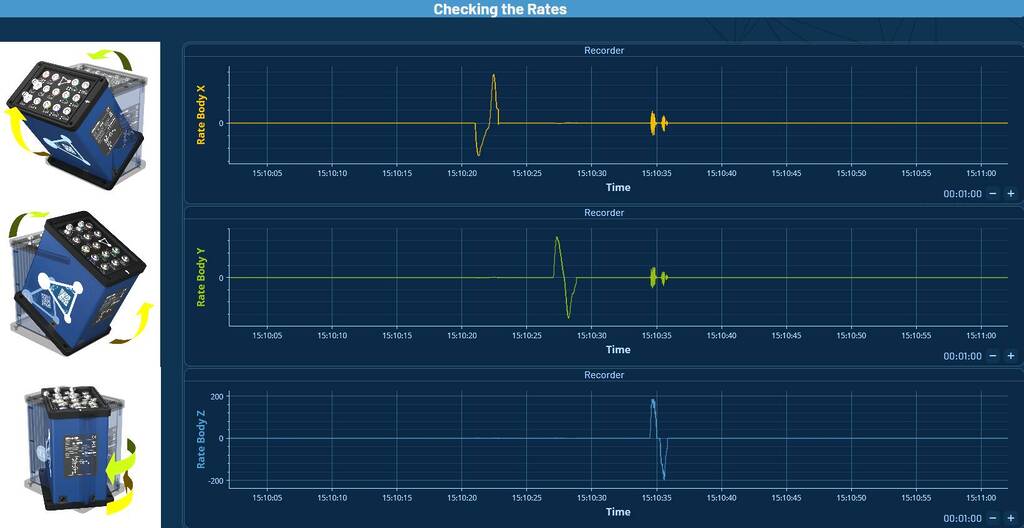
This data plot shows that ADMA detects negative as well as positive rotational speeds about all three measurement axes.
Checking the accelerations
The system should be move linearly along the individual axes in the sequence X, Y and Z.
The plotted data could appear as follows:
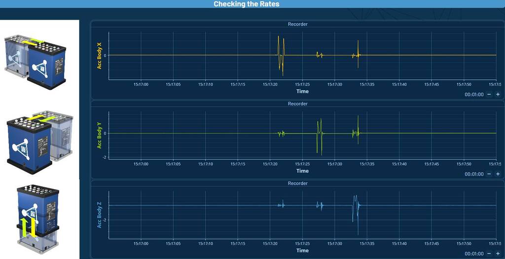
This data plot shows that ADMA detects negative as well as positive accelerations along the three measurement axes.


